Tuesday, February 19, 2013

Rudder cheeks and boomkin installed!

Finally, I was able to get the rudder cheeks and boomkin installed. It seemed like a long time to get this task completed. Now I just need to pull a few chain plates and see how they look. Then that will complete the standing rigging system for now. I plan on changing out all the standing rigging cables in a few years. I will inspect them all just in case..

I did replace the boomkin tangs, stays (cables) and turn buckles as you will see below.


The easy bolts first.

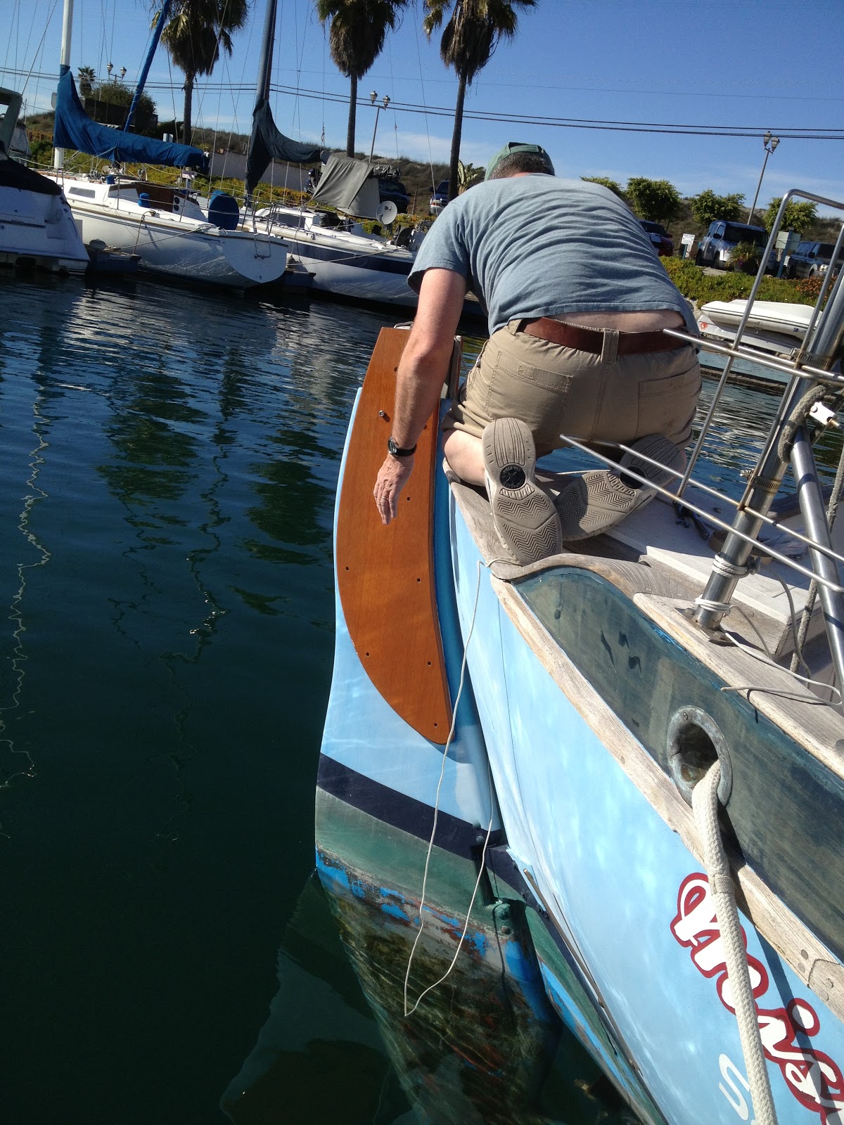
My best view!

Too long in this position and the ice tea wants to come back up!

Just a nice picture with palm trees in the background.

Gratuitous wiener dog pictures for Nancy! Miss Mae enjoying the sun.

And when she gets too warm.

The old versus the newboomkin tangs. FYI these old tangs were known for breaking and bringing down a mast or two. It was a no brainer to replace them. They would break at the top hole in the picture. There is very little metal there for how much tension the get.

The old ones didn't leak. Do you think I need a bottom paint job!

New tang and stay installed. I had the rope tied to it in case I dropped it while installing it.

And the cheeks installed and the boomkin installed with the back stay attached. (The back stay is the "cable" coming from the middle top of the picture to the end of the boomkin...it holds up the mast.)
See the rope hanging off the end and going into the water? Yeah, well, that is for the diver so he knows where to look for my craftsman 3/8" ratchet and socket that decided to jump out of my hands! Did I tie a rope to that...nooo, I won't drop it. I'll be "careful".  (Curtis this is all your fault...this is what we were talking about this weekend!)
By the way the diver that cleans my hull will fetch my dropped items for free...if he can find them! Maybe he can pick up my $12 stainless bolt and rubber sanding block from a few months ago too. They say global warming is causing the ocean level to rise....it is actually me just dropping stuff that is raising the ocean level. Sorry Mr. Gore!
 
I know the wiener dog floats......don't ask.

Thursday, February 14, 2013

Cetol(ing) the rudder cheeks and boomkin

Just so you know I'm not slacking off after work I get home and put one layer of cetol on each night. Here is how the layer count goes:

Rudder cheeks = 2 coats of penetrating epoxy, 2 coats of cetol teak light and 3 coats of cetol gloss. They are done.!
Boomkin and the six boomkin spacer blocks = 2 coats of penetrating epoxy, 2 coats of cetol teak light. Only 3 coats of cetol gloss to go before I can install them! Maybe I can get it installed on Sunday or Monday. That would be nice!


Tuesday, February 12, 2013

Engine Pan Liner Top... making progress

Two posts ago I showed you how I cut up the engine pan. I had already cut the new tops and coated them with penetrating epoxy getting them ready to install. This last weekend I worked on the boat in the engine room again. I cut a bit more of the fiberglass pan of in order to give the engine more room and to make it look like it was not done by a complete amateur. (But it was....me.)  I made a ton of dust again cutting out just a few pieces. Amazing how "dusty" fiberglass gets when cut.

Here is a picture as I left it before the new cuts then a picture with the new cuts.


You can see I removed more from the aft end.
 
I cut two stringers to mount just a bit below the height of the remaining pan on the hull. This stringer was attached with thickened epoxy to hull sides. I used a lot of thickened epoxy to build up a ledge for the stringer to "sit" on and support the plywood at the hull. I then used thickened epoxy and covered the stringers with it and the pan where the plywood sits on it. I was generous with the epoxy to make sure the plywood was sitting in a lot of it to bond it well. FYI, I did scuff up the hull with the grinder and sanded the other areas with 60 grit so the epoxy had something to bite into as it cured. But it was taking a long time to cure by now as the temps were in the low 60's. 
You can see the fillets of epoxy between the hull and the 3/4" plywood.
 
I left the epoxy to cure and will come back this week sometime to apply several layers of cloth to tie it all together as one big piece.
 
One last thought. I will end up cutting my cockpit hatch in two. That thing is heavy and cumbersome to lift. I can't see having to remove it if needed in a seaway. It would be difficult at best! But that will have to wait. I want to get my engine installed!!!!


Wednesday, February 6, 2013

Finally getting to the rudder cheeks and boomkin again

Man it seems like time is flying by and passing me up. I picked up my rudder cheeks and boomkins right before Christmas and here it is early February!  Sunday before the super bowl I gave them all a coat of penetrating epoxy. This was the second coat for the cheeks and the first for the boomkin. Monday night I went out and took the cheeks and boomkins down from their hanging position in the garage last night to wash the epoxy blush off. This time I didn't wash them in the kitchen sink! You can read about that here.

 I hung the boomkins back up and gave them another coat of penetrating epoxy. The last one for them before they get the cetol. The cheeks I sanded them down to get the drips and runs out (How could I get drips and runs when I was thinking I didn't put enough epoxy on?) to prepare them for the gazillion six coats of cetol I need to put on. I am going to do the top, let them dry then do the bottom. So this should take some time. I really want to try and get a nice smooth finish on the cheeks and I'm not so good at smooth. So we'll see how they turn out. the main thing is that they get protected. We all know protection doesn't have to be pretty.....right?

Here is the boomkin hanging with it's second coat of epoxy drying.
Sorry about all the clutter in the background...I'm building a boat!


And the cheeks with their first coat of cetol teak light. They "look" OK now, lets see tomorrow.
Look in the upper left corner you can see the engine pan tops. I also coated them with penetrating epoxy on Sunday.

Stay tuned and watch epoxy dry!


Tuesday, February 5, 2013

Cutting the engine room liner.

I made a template of my motor with the mounts attached so I could use that to see how high or low I needed to raise the engine bed. (You know the part that the engine bolts to. Patty B. that was for you!)
You can see the engine mounts under the wood and the wooden dowel is the center line of the transmission. That is where the propeller shaft and the engine need to line up. The engine and the propeller shaft need to be within thousands of an inch to be done correctly. This will keep the engine vibrations down to a minimum. (I want smooooth sailing, uh ok motoring also.)

I took it to the boat and give it a try figuring the difference would not be to much.
Yeah, no. I will have to move the engine forward and down about two inches. The engine mounts are at the bottom of their travel so they will not go any lower.Mmmmm what to do? I figure I will try and cut out just the sides to see if that would at least give me more room to move the engine back to line up with the shaft. It can't hurt I have to lower the engine somehow.
 

No luck, you can see I still have a ways to go down.

What's next...major surgery of course! I measure how low I need to go and then add some to that just in case. I made a ton of fiberglass dust cutting the fiberglass with a 4" grinder and a sawsall. I had on a good respirator and a long sleeve shirt and a hat to keep the "pricklies" down to a minimum. After the dust settled this is what I have left of the pan. Why, you ask, don't I just cut out the whole pan? Well I really want a pan to catch any oil drips from the engine. That way it keeps it out of the bilge and out of the ocean. ($$$ in fines!) I thought you would see it my way.
Here is what was left.

Sorry the picture is a little "cloudy". I guess the air had not yet cleared.

I then proceed to make new "beds" for the mounts to mount on. Here is what they look like.


I still need to cut off the fiberglass that is on the sides in the lower part of the picture. I will take the new beds home and fiberglass them with cloth. I'll bring them back and then fiberglass then to the boat and to the pan. I used 3/4" plywood for these beds. The ones I cut out were 1/2" plywood. I think this would be better plus the new engine weights about 100 pounds less than the old one. So I should be good.

Here is the engine mock up sitting on the "new" pan tops. They have not been glassed in yet. Still just test fitting.  I still do not like the finial location of the engine as it is really close to the forward bulkhead. But you can see the shafts lined up nice! I still have some tweaking to do to get it in it's final location. That will have to wait for next weekend.

Monday, January 28, 2013

cockpit drains.....into the engine room not over board

I have noticed that over the last few months that if we get a heavy dew there will be water in the engine room pan. Well when it rained the other day the pan was about  half full.

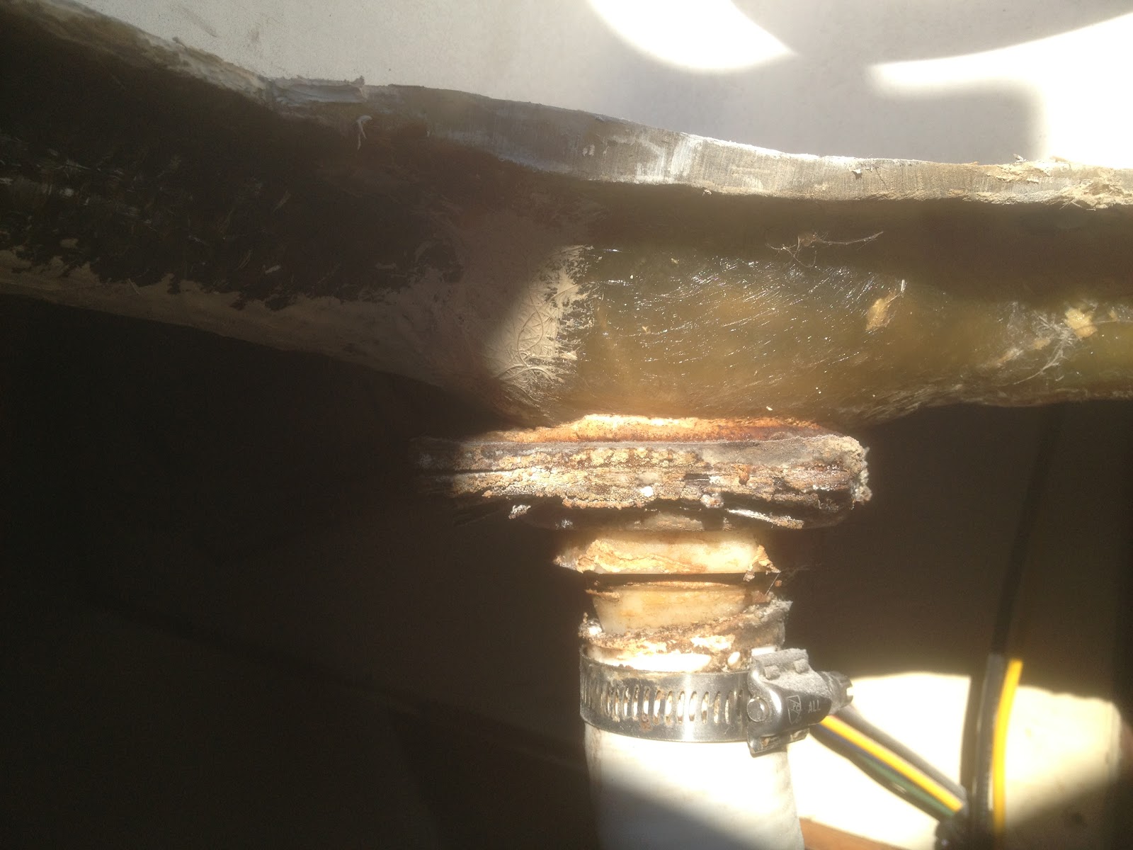
The other day I was at the boat when it was raining just a bit. I looked into the engine room to see where the was was coming from. I saw water running down the two cockpit drain hoses then into the engine room pan. Then it occurred to me that this is how the original Volvo engine came to rust out from the bottom. The previous owners never took the water out of the engine room pan when it filled up. They just let the engine sit for years in what ever water would collect there. Poor little engine had only 45 hours on it too. After seeing the amount of water that collected just from a light rain it all made sense.

Here is what the backing wood looked like.

Here is what it looked like when I removed it. A wet soggy mess that just fell apart.
And now the new improved version.

I removed and cleaned the drain and re-caulked both sides of it and made a new wood backer. I didn't have any epoxy with me so I just painted it with three coats of rustoleum enamel. That should hold until I can make new ones coated with epoxy.

It rained that night a good bit. When I went to the boat the next day the engine room pan was as dry as I left it. So no more leaks from the cockpit drains.

Update: As I read what I wrote it sounds like the cockpit drains run into the engine room pan. They do not, they run into thru-hulls. But the water leaked so bad the water ran on the outside of the hoses and not the inside. Thus all the water in the pan.  Sorry for the confussion.

Thanks Skip!

Friday, January 18, 2013

Windlass Installed!

Last night after work I headed to the boat to install the windlass. Deena met me there with all the items I would need to mount the windlass. I removed two of the three bronze bolts that hold the bowsprit on. I will use these to hold the windlass plate on plus I will install a 4" lag bolt in the middle of the 10 ga. stainless steel plate for additional strength. The pic below shows the game plan. You can see that I have butyl tape as the sealant.
 
The next shot shows the plate mounted. I see that a lot of people mount the windlass more to the starboard side to line up with the existing opening in the deck. I chose to move the opening in line with the bow roller. This allowed me two things, first the pull of the chain from the bow roller to the windlass down to the chain locker deck opening will all be in line. (The blue tape is covering the opening.) I plan on having an all chain rode on this side so I hope them all being in line will help. I also installed a chain pipe which you can see here. Second on the port side I will cut an opening (Nellie Jo only has one hole for the anchor for now.) for a mostly rope anchor line to go below into the rope locker.
 
 I did install a second bow roller when I replaced the bowsprit so I could carry two anchors if I want to.
Here is the final install. It was dark by the time I finished. By I'm glad to be done with this project.


Thursday, January 17, 2013

How to build a boat in your kitchen and other stuff.

First the other stuff, then building a boat in the kitchen...
Yesterday I wrote about the raw water pump and how little space there is to remove the impeller. Well here is a picture.
There is 3 1/2" of space to pull the plate off and pull the impeller out. Not much....plus it will have to be done in the confines of the engine room.

The completed painted windlass. It looks much better now. It took a bit of sanding and chipping to remove the paint but it looks like it was worth it to me. Some of the chrome was flaking off so I tried to remove as much of it as I could. The chrome was over bronze so I will not lose any protection for the parts I removed it from.
Your so pretty...oh so pretty.

Aluminum for the engine mounts. I went to Industrial Metal Supply yesterday and scored a bunch of 6061 alloy (structural marine grade alloy) 1/2" thick by 3" wide stock. I need two pieces about 28" long for the the bed rails and a few 6" pieces for spacers. The nice thing is all theses pieces were remnants so that kept the price very low. The smaller pieces are all 12" long so I can get two spacers out of each one. Plus the long ones will have at least one spacer as a drop off after I cut them to size.
 
 
How to build a boat in the kitchen of your house...OK not build the whole boat or even build a part of the boat. How about how to use your wife's kitchen while see is at work and not tell her. She will find out soon enough when she reads the blog.....this might be my last entry.....we'll see.
OK so its cold here I'm talking in the high 30's. Yes in southern California, whats up with that and where is the climate warming when I need it? Al Gore you lied! Oh sorry back to the kitchen. If you remember I have my rudder cheeks and boomkin back from H&L Marine. I put a coat of penetrating epoxy on the cheeks and now needed to wash off the blush (waxy stuff that is left on the epoxy when it dries) so I can put another coat on. Remember how cold it was, well I'm not going to open up the garage and wash off the cheeks in the cold, no way I'm a whimp. What to do? I need warm water and a warm place to wash the blush off the cheeks. Deena (the afore mentioned wife) is not home and the kitchen has warm water and it's warm in the house. Problem solved!
 
Ohh look at the suds on those cheeks! Hey the rudder cheeks! Any way I barely got them both washed and dried and sitting by the back door when Deena walked in. Oh shoot! I didn't make a clean escape! While she set here stuff down I grabbed the cheeks and hauled buns out to the garage...all of about eight feet. OK I'm safe for now....

While in the kitchen grab a bunch of baggies. They make great organizers for holding small stuff, like bolts, etc. Just write what they go to on the bag and toss them on the shelf. That way you don't have to try and remember what this or that went to...just read!

This weekend I will head to to boat to install some of this stuff and remove the engine gauges. I want to see if I can reuse some of the gauges instead of having to buy new ones. New ones =$$$  Me = cheap!

Wednesday, January 16, 2013

Engine Paint and Raw Water Pump

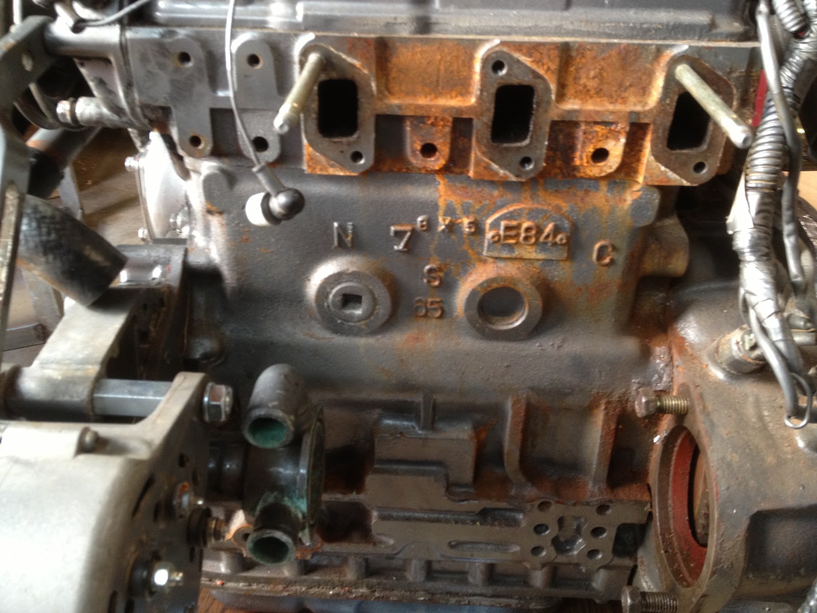
I am trying to get my engine ready to drop into the boat. (I have to get the boat ready too!) The engine when I bought it had a missing heat exchanger. The heat exchanger has rusted through due to having seawater(raw water) sit in it for a long time. You can see in the picture below that the block had a little bit of rusting and staining from the heat exchanger.
I think that a clean engine is helpful as you can see when leaks start etc. So I need to clean the rust and paint it. I sanded off any of the chunky rust which there was very little. Mostly it was paint that had lifted from the rust below it. I taped off the exhaust ports then I painted on a rust converter and let it sit overnight.
Last night I went out and warmed up the garage. It was in the low 40's here! Brrrr. Then pulled out the Yanmar gray paint. Or not! Yanmar wants $16 for a single can of spray paint! $16 bucks I don't think so! Home Depot sells Yanmar gray as gray Rustoleum for $4 a can. Yea I went with Rustoleum, call me cheap. But hey they use this paint on oil rigs so it has to be good right?  I had a few pieces off the engine that needed paint too so I went crazy and sprayed them too. (By going crazy and painting parts you can imagine how "wild" my life is! OK back to the boring stuff.) Here is a picture of the new shiny parts.

Oh look there is the alternator spacer I said I had to paint. (Fourth item up.)(Look at the extremely boring post before this one!)

The raw water pump. people complain about the raw water pump being hard to get to on this engine. I can see why. The starter is only a few inches from it so it is difficult to access it and get the impeller out. I'll work out some way to make it easier to get to so if I have to do it in a seaway I will be able to without to many bad words spewing from me. Oh and  I think I will get some extra screws for the cover as they are small and I know I WILL drop them into the bilge never to see them again.
Anyway I pull the cover off the raw water pump and see the impeller looks to be in OK shape. There are only a few nicks in it but all the vanes are there. My impeller just pulls out with no "C" clip or retention device to make the job harder.

But my real question here is the pump housing. It appears that the impeller sat for a while. There is a bit of evenly spaced "lumps" in it. I'm not sure it is corrosion as much as it is just dried seawater. You know how it leaves a hard residue or better yet a scale? The amount is really small as far as now pronounced it is, but should I try and remove it? See the green lines? That is what I am talking about.
So let me know what you guys think. I know there has to be a few good marine mechanics out there!

Thursday, January 10, 2013

Alternator spacer - really, 3 months to get one?

As you know I bought a barely used Yanmar 40 hp diesel motor to put in the boat. One of the things it was missing was the bolts to bolt on the alternator. I being one who likes to research the death out of something before I buy downloaded a parts catalog for my engine. I see that I need a spacer for the alternator lower bolt. This is similar to a car for all you gearheads out there. I called my local and great Yanmar dealer, Boatswain's Locker. By the way I have to give a big thank you to Jerry the parts manager who works there. He stays late to help me because I can't always get there before they close due to traffic.(Welcome to SoCal!) Any way I call and ask for the spacer...not in stock and it will take 3 months to get here. Hahaha, good one , now really when can I pick it up?  3 months. Really! I am so used to just walking in and getting something or at the most wait 3 week, much less 3 MONTHS!

OK I can't wait that long. The spacer is actually a long threaded nut that has two bolts that thread into it on either end to hold up the alternator and make the "swing" portion or hinge so the alternator can be moved so the belt can be tightened. OK enough with the mechanical lessons. Lets move on to fixing the problem of not having this 3 month item that I need NOW.

I take a few pictures of the area where the alternator mounts, get a few measurements, grab the alternator and head to the hardware store, Cannings Ace Hardware in La Habra. I love this store the guys there are the ones who will help you figure out how get something done as opposed to the big orange store that has guys in it that keep telling me "You can't do that".  By the way if you have to go to the big box store make sure you know what you need before you get there. If you try and figure out how to fix (read: jury rig) while you are there it is very distracting to have some one keep telling you "you can't do that". (Opps that was a rant I think...) Any way I grab a bolt that will be as long and big as the spacer and two bolts that originally were used, then a rod coupling that will allow the bolt to pass through it. Plus some the nuts, washers etc that I need.
Here is the "spacer" a rod coupling.
I head home and start the "build". Sounds impressive the build...don't worry you will be disappointed when all I did way cut a rod coupling down. So I take the coupling to the engine and hold the alternator up in the correct position to see how much of the rod coupling I have to cut off.
How do I cut off?

Now the action pictures of me cutting it down and grinding the end to the final length. I don't have a picture but I did take a file to it and smooth off and round the edges so my soft little hands won't get cut.

Wooo...look at the sparks fly I should be an action photographer!  Yes big brother (Not you Bubba, the government.) (FYI Bubba IS my brother...I was raised in the south!) I had all the required personal safety gear on.
And the final fit.
It fits! The bolt will go through the coupling when assembled..

Now my engine is starting to actually look like an engine!
Now tell me, was all the reading and pictures really required to say I cut a coupling down?
I didn't think so.....

Oh I have to paint the part so it matches the rest of the engine....yea I'm anal that way.


Tuesday, January 8, 2013

Back to work on the boat-Motor and Windlass mount

Not much was done on the boat this last month due to Christmas. But the plus side is all my kids came home so I was able to spend time with them all. (All both of them!) Dang I miss them!

I'm trying to get the engine complete as there are some small things I need to take care of. One of the items is the spacer that goes on the alternator. It has to be ordered from Japan and will take several months to get here. I think I will find some kind of different spacer to use. I think I will use a threaded coupler that is used for all thread rod.
The poor picture above is for the bottom bolt length. This is were I need the spacer.
The picture below is the upper bolt That I need. I put a long one in just to hold the alternator in place while I test fit the belt.
I still need a control panel for the engine. I found a place in Florida that might have a used panel. I would like to use my existing gauges if possible but know if I could. Anyone know if I can use my old gauges? Below is the picture I'll send to the shop to see if the panel they have will work.
I bought the bolts I needed to mount the windlass on the mounting plate that was made for me. I drilled the mounting holes tonight. It was a bit of a problem as I did not have the correct size bit. I ended up using a unibit to finish the holes but I burned up the bit going through the stainless steel plate. Here are a couple of pictures of the plate and the test fit of the bolts.


That's it for now. Work should pick up again on the boat so stay tuned! I hope to start making the hawser pipe fiberglass tubes tomorrow.